- Parallel projection. Orthographic projection. Multiview projection, including: Plan view or floor plan view. Elevation, usually a side view of an exterior.
- Perspective projection, including: One-point perspective. Two-point perspective. Three-point perspective.
.
Regarding this, how do you read a CAD drawing?
How to Read CAD House Plan Drawings
- Look at the legend. The legend or key, usually located near the lower right-hand corner of the drawing, should explain all of the symbols on the drawing.
- Look at the title block.
- Read the notes.
- Pay attention to lines.
Additionally, what are the 4 basic components of an engineering drawing? The main purpose of engineering drawings is to communicate to other engineers, machinists, etc.
Dimensions have four basic components:
- Dimension Text.
- Dimension Line andArrows.
- Extension Lines.
- Gap.
One may also ask, what is the Third Angle Projection?
The plane of projection is assumed to be transparent. When view are drawn in their relative position Top view comes above Front view, Right side view drawn to the right side of elevation. A Third Angle Projection drawing is identified by the third angle projection symbol.
What is basic technical drawing?
Technical drawing, drafting or drawing, is the act and discipline of composing drawings that visually communicate how something functions or is constructed.
Related Question AnswersWhat is a drawing number?
It has the form of either 4-digit or 7-digit drawing number that completely defines a particular device. Each drawing number can then accommodate many sheets but ALL sheets in a given drawing number are the same physical size; A, B, C, D, or E sized.Is engineering drawing hard?
Engineering drawings are not that much difficult, if you have a good imagination power and a lot of patience. If you want to be a good in drawing/drafting, then first learn the basics first and always practice to draw smaller objects.What is the purpose of a technical drawing?
technical drawing. Technical drawing is a drawing or plan, rendered to scale, that is used to communicate direction and specifics to a group of people who are creating something to explain how something works or how to build something.What is meant by engineering drawing?
An engineering drawing, a type of technical drawing, is used to fully and clearly define requirements for engineered items. More than merely the drawing of pictures, it is also a language—a graphical language that communicates ideas and information from one mind to another.How do you read architectural drawings?
The Basics: How to Read Architectural Plans- Be organized and diligent when reading plans. Start in upper left corner and work way across page so as not to miss any details.
- Read the plan cover sheet.
- There are often reference points that are used between professionals and sets of drawings.
- Review the plan index which provides a list of all plan sheets.
Why are symbols used in engineering drawings?
Engineering drawing abbreviations and symbols are used to communicate and detail the characteristics of an engineering drawing. Many corporations have such standards, which define some terms and symbols specific to them; on the national and international level, ASME standard Y14. 38 is one of the widely used standards.What is AutoCAD drawing?
AutoCAD is a computer-aided tool that allows many different types of designers to create diverse kinds of drawings and designs. This program helps designers create their designs much more quickly than by hand and offers many quick, easy, and useful features, such as copy and paste.What is technical drawing and design?
Technical drawings are intended to convey one specific meaning, as opposed to artistic drawings which are expressive and may be interpreted in a number of ways. Most drawings prepared during the design and construction of buildings might be considered to be technical drawings.How do you draw a cartoon book?
Here are the steps to draw Cartoon Book. Enjoy!- Step 1: Draw rectangle as the cover of the book.
- Step 2: Draw a narrow rectangle to make the book look thicker.
- Step 3: Draw another rectangle connected with 2 existing rectangle.
- Step 4: Draw some lines to make it look like the pages of the book.
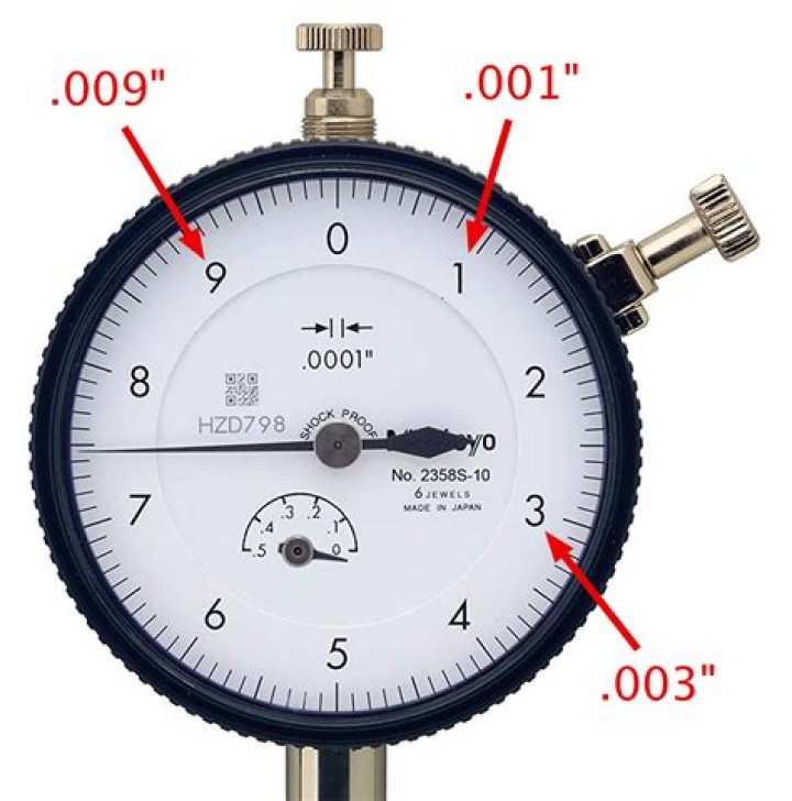
How do you read a micrometer?
To read the micrometer in thousandths, multiply the number of vertical divisions visible on the sleeve by 0.025", and to this add the number of thousandths indicated by the line on the thimble which best coincides with the central long line on the sleeve.How do you read a carpentry blueprint?
Steps- Read the title block. These often appear at the beginning of any blueprints.
- Read the revision block.
- Read the notes and legend.
- Determine the view.
- Establish the scale in your mind.
- Inspect the grid system.
- Locate any doors and windows.
- Identify any appliances.
How do blueprints work?
A blueprint is a reproduction of a technical drawing, documenting an architecture or an engineering design, using a contact print process on light-sensitive sheets. Introduced in the 19th century, the process allowed rapid and accurate reproduction of documents used in construction and industry.What is a plan and profile drawing?
The plan and profile sheet is a type of engineering drawing, traditionally prepared in CAD, that combines a plan view, a map that targets a linear feature such as a levee, road, or channel, with a profile view, an XY plot of the elevation of the targeted linear feature.How are blueprints made?
The blueprint process The best known is a process using ammonium ferric citrate and potassium ferricyanide. The paper is impregnated with a solution of ammonium ferric citrate and dried. Excess ammonium ferric citrate and potassium ferricyanide are then washed away. The process is also known as cyanotype.How do you draw a floor plan by hand?
- Step 1: Engineering Scale Tutorial. Here's a quick tutorial on how to use an engineering scale.
- Sketch Exterior Walls.
- Step 3: Draw Reference Lines.
- Step 4: Interior Walls.
- Step 5: Locate Doors.
- Step 6: Add Windows.
- Step 7: Place Cabinets, Kitchen Appliances and Bathroom Fixtures.
- Step 8: Dimension the Plan.