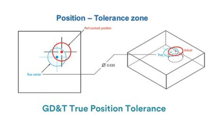
The True Position is the exact coordinate, or location defined by basic dimensions or other means that represents the nominal value. In other words, the GD&T “Position” Tolerance is how far your features location can vary from its “True Position”..
Moreover, how does GD&T calculate true position?
True position is the deviation between the theoretical position on a drawing and the actual position, measured as the centerline, on the final product. True position can be calculated using the following formula: true position = 2 x (dx^2 + dy^2)^1/2.
Also Know, what does the U mean in GD&T? The (U) symbol is introduced in Y14. 41-2003 DIGITAL PRODUCT DEFINITION DATA PRACTICES and it has been adopted in the Y14. 5M-2008. The number preceeding the (U) symbol is the total profile tolerance and the number following the (U) symbol is the amount of tolerance allocated on the plus material side.
Just so, what is the difference between true position and concentricity?
While true position is usually controlled to a fixed point in space that forms from coordinate measurements from a datum, concentricity is controlled to the axis derived from an all the median points of a datum surface or feature.
What are the 3 types of tolerances?
Three basic tolerances that occur most often on working drawings are: limit dimensions, unilateral, and bilateral tolerances. Limit dimensions are two dimensional values stacked on top of each other.
Related Question Answers
Does true position control perpendicularity?
True Position using features of size (MMC/LMC) However, with true position you can make the tolerance referenced to several datum's as opposed to just one with axis perpendicularity. When you callout true position using datums on the face, and sides of the part – perpendicularity is controlled as well.What is a basic tolerance?
Basic Dimension – GD&T Defined. Basic dimension: A basic dimension is a numerical value used to describe the theoretically exact size, profile, orientation, or location of a feature or datum target. The tolerance associated with a basic dimension usually appears in a feature control frame or a note.What is position tolerance in GD&T?
In GD&T, position is a versatile tolerance that can be used to control location, coaxiality, orientation or axis offset of a part feature or axis. Position tolerance is generally applied to features important to assembly like holes or slots, and it is often included when performing a tolerance stack.What is MMC and LMC?
MMC is the condition of a feature which contains the maximum amount of material, that is, the smallest hole or largest pin, within the stated limits of size. LMC is the condition in which there is the least amount of material, the largest hole or smallest pin, within the stated limits of size.How do I use GD&T?
General Approach to Applying GD&T to a Design Model - Step 1: Application of GD&T with established Datum Reference. The first step in applying GD&T to a design model is to establish a datum reference frame (DRF).
- Step 2: Application of GD&T to constrain attributes of features.
What is tolerance in drawing?
Tolerance is the total amount a dimension may vary and is the difference between the maximum and minimum limits. Tolerance = 0,3 mm. Tolerances are represented as Tolerance Values (A) or as Direct Limits (B).How do you type the symbol for true position?
U+2316 was added to Unicode in version 1.1 (1993). It belongs to the block Miscellaneous Technical in the Basic Multilingual Plane. This character is a Other Symbol and is commonly used, that is, in no specific script. The character is also known as true position.What is profile tolerance?
In GD&T, profile tolerance defines a uniform boundary around a surface within which the elements of the surface must lie. Profile is a complex tolerance that simultaneously controls a feature's form, size, orientation, and sometimes location. The top figure shows the profile tolerance applied to a curved surface.What is runout GD&T?
In GD&T, runout tolerance is used to control the location of a circular part feature relative to its axis. This is different than circularity, which controls overall roundness. Runout helps to limit the axis offset of two parts to ensure they can spin and wear evenly. An example of runout tolerance is shown below.How do you measure perpendicularity?
Perpendicularity is measured using a height gauge, similar to flatness, however, the gauge (or part) is locked to a 90° datum to measure how perpendicular the surface is. The entire surface has to be measured if it is a flat feature. See Example #2 below for a good example Axis Perpendicularity using MMC.How do you measure concentricity?
Unlike with coaxiality, you measure the circle of the plane. Put the stylus on the measurement point on the datum circle, and then put the stylus on the measurement point on the target circle to measure the concentricity. The stylus only comes into light contact with the surface and does not scratch the target.Is concentricity the same as runout?
Concentricity is the derived centerpoint/line between two objects that NOMINALLY share a center. It has no form control. Only location. Runout is the deviation from NOMINAL form about a centerline (often not its own centerline) which controls both form and location.What does M mean in GD&T?
In GD&T, maximum material condition (MMC) refers to a feature-of-size that contains the greatest amount of material, yet remains within its tolerance zone. Some examples of MMC include: Largest pin diameter.How do you test for flatness?
Flatness is can be measured using a height gauge run across the surface of the part if only the reference feature is held parallel. You are trying making sure that any point along the surface does not go above or below the tolerance zone.What do GD&T symbols mean?
Geometric dimensioning and tolerancing (GD&T) is a system for defining and communicating engineering tolerances. It uses a symbolic language on engineering drawings and computer-generated three-dimensional solid models that explicitly describe nominal geometry and its allowable variation.Why is GD&T important?
GD&T, a vital part of complex machining, offers a number of major advantages: Saving Money — GD&T enhances design accuracy by allowing for appropriate tolerances that maximize production. For many projects, the process provides extra or bonus tolerances, further increasing cost effectiveness.How many GD&T symbols are there?
fourteen GD&T
What is the symbol for depth?
Depth/Deep - is used to indicate that a dimension applies to the depth of a feature. This symbol precedes the depth value with no space in between. Diameter - indicates a circular feature when used on the field of a drawing or indicates that the tolerance is diametrical when used in a feature control frame.What is a feature of size?
In GD&T the term feature-of-size (FOS) refers to any surface, or set of parallel surfaces associated with a size dimension. Specific examples of features of size include: A hole diameter (a cylindrical surface) Plate thickness (two opposed parallel surfaces)